
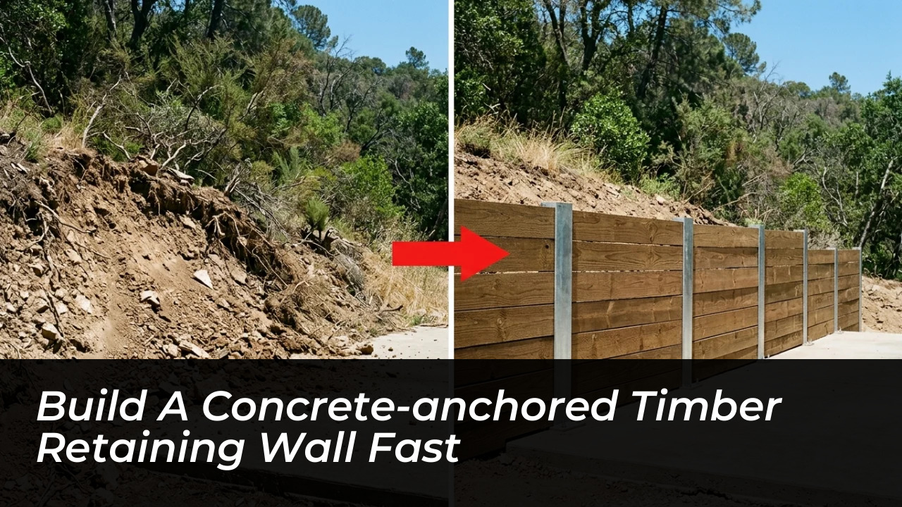

Facing persistent hillside erosion along a paved 1952-era driveway, a Mountain West homeowner engineered an innovative solution that bypassed traditional trenching and heavy excavation. By anchoring custom steel uprights directly into an existing six-inch concrete driveway slab, the builder erected a robust, straight timber retaining wall section in under four hours while preserving maximum vehicle clearance.
For decades, loose soil, exposed tree roots, and rocks crumbled directly onto the edge of the paved driveway. Traditional masonry block walls or standard earth-buried wooden posts would have demanded deep trenching or eaten up inches of critical clearance beside the vehicle path. Instead, this hybrid approach paired locally fabricated steel posts with durable 6×6-inch timbers to hold back the eroding bank.
The Structural Engineering Behind Slab-Mounted Steel Channels
A persistent myth in residential landscaping assumes that retaining walls must either sit on a buried footing or feature timber posts sunk deep into the native subsoil. When an existing, structurally sound concrete slab is already present, engineered mechanical fasteners can transfer lateral earth pressure directly into the slab mass.
The builder turned to a local welder to fabricate custom vertical uprights based on an I-beam channel profile. Each upright incorporates an integrated horizontal base foot designed to sit flush against the concrete edge. Drilling the eight required 5/8-inch anchor holes into the six-inch slab took less than an hour using an electric rotary hammer drill, securing the skeleton of the wall with heavy-duty mechanical expansion anchors.
Precision Fitting and Timber Weatherproofing
The internal channels of the steel uprights were dimensioned to fit nominal 6x6x8-foot ground-contact pressure-treated timbers. Because true dimensional lumber often varies, measuring approximately 5.5 inches across, a cordless hand planer was used to trim roughly a quarter inch off the wood ends so they could slide effortlessly into the steel tracks.
To resist wood decay from continuous soil contact, the hidden back faces of each timber received a heavy coating of asphalt fence-post sealant prior to placement against the bank. The timber tiers were then secured to one another using eight-inch TimberLOK heavy-duty structural wood screws, creating an interconnected monolithic barrier between posts.
Retaining Wall Technical Specifications
Understanding the exact materials and layout reveals why the design performs well under lateral loads while remaining modular for long-term ownership.
- Primary Uprights: Custom steel I-beam channels with welded base plates
- Slab Fasteners: Two 5/8-inch mechanical expansion anchors per post
- Wall Beams: Ground-contact pressure-treated 6x6x8-foot lumber
- Fastening Hardware: 8-inch TimberLOK heavy-duty structural wood screws
- Moisture Protection: Asphalt fence-post sealant on soil-facing timber surfaces
- Top Finish: 2×8-inch continuous dimensional capping board
- Retained Backfill: Native decomposed granite soil containing 15% clay
How the Modular Wall System Was Constructed
Executing this structure followed a sequential method designed to verify alignment before securing permanent fasteners:
- Substrate Preparation: Clear loose hillside scree, surface dirt, and exposed organic debris away from the concrete slab interface.
- Anchor Installation: Position the steel feet, drill 5/8-inch holes to depth in the six-inch slab, and torque down the expansion bolts.
- Timber Milling: Plane the beam ends by approximately 1/4 inch to match the internal width of the steel I-beam flanges.
- Protective Coating: Apply asphalt sealant across the back face of every timber designated for ground contact.
- Stacking and Fastening: Slide horizontal beams into place, joining consecutive tiers with eight-inch structural screws.
- Top Capping: Fasten a continuous 2×8 board over the assembly to seal vertical seams and shield timber end grain from moisture.
Drainage Dynamics and Hillside Gravel Steps
Hydrostatic pressure remains the primary failure mechanism for retaining structures worldwide. While typical installations require dedicated perforated drain pipes and aggregate backfill, this installation adapted to unique environmental conditions. Located in the semi-arid Mountain West, site soil tests showed decomposed granite mixed with 15% clay. Because the existing driveway concrete was poured with an intentional grade sloping away from the bank, runoff naturally sheds outward, and surplus moisture can exit underneath the bottom timber run without pooling behind the structure.
At the wall’s terminus beside the residence, the homeowner adapted the timber framework into an integrated flight of stairs over three partial workdays. Using identical 6×6 lumber, broad terraced boxes were constructed to contour with the natural hillside ascent. Filling these stepped timber frames with tightly compacted gravel formed stable, porous treads that eliminate mud and grant easy foot access to upper property elevations without pouring supplementary concrete footings.
Long-Term Maintenance and Structural Advantages
A major flaw of conventional timber walls is post rotting beneath the ground line, which forces homeowners to demolish the entire barrier when wood fails. In this hybrid design, the structural load rests on external steel uprights that remain visible and completely out of subterranean wet zones. If an individual timber course degrades over time, the homeowner can unscrew the 2×8 cap, slide out the damaged beam, and slot in a new pressure-treated board without disturbing the slab anchor points or excavating the hillside.